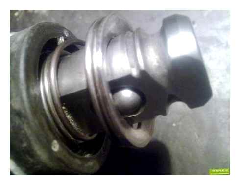
How to Disassemble a Peorator
Disassemble the concentrator one after the other. Carefully inspect all parts. Even if you are looking for a problem in one part, you can find the damaged parts in other parts. When disassembling the tool you should clean the housing from dust and dirty grease.
How to disassemble a chuck and remove a jammed tool
Start by disassembling the cartridge so that it does not interfere with the removal of the firing pin housing.
Bosch Hammer Drill Refreshment | Bosch GBH 2-24 DSR disassemble

If you can not get the drill bit or other accessories out of the chuck, there are two ways to solve the problem:
- Clamp the tool in a vice. Pull the chuck slightly sideways while wiggling it;
- Clamp the tool in a vice using the rubber gaskets so as not to damage the plastic housing. Use a torque wrench to clamp the end of the bit. Tap with a hammer on the wrench in the direction of the tool axis.
The second option is used as a last resort. If after several strokes the drill or chisel cannot be pulled out, stop. You can damage the feed dog. Disassemble the cartridge and gearbox. Try to knock out the tool using the punch. After this procedure you will most likely need to replace the bushing. To avoid this problem in the future, lubricate the end of the tool.
How to remove the mode switch
On some models of the machine the switch is removed by turning it to the extreme right position, on others it is removed to the extreme left position. Consider far right position.
Disassembling the mechanics
- Remove plastic gear case. You will see an aluminum housing with a drunken bearing inserted, an intermediate shaft, a raster bushing.
Important differences in the design of the Bosch torches
If you are repairing a Bosch peorator, you will need an electrical and disassembly diagram for the model you are going to repair.
Electrical schematics of crosscut saws Bosch 2-20, 2-24, 2-26 are almost identical. Although there are some non-principled differences.
The mechanical units, on the other hand, are assembled with parts that differ in construction. The main differences are assembled in two nodes: the intermediate shaft and the shaft of the drum unit.
The biggest differences are in the designs of the intermediate shaft, the “drunken bearing” assembly, the mode switch. There are some unprincipled differences in the striker, firing pin, striker unit and firing pin.
Disassembly of the shock mechanism assembly
With the Bosch 2-26 upright on the handle, unscrew the four screws pos.90 holding the cover of the mechanical housing.
Press on the end of the striker shaft and remove the cover. The cover is black plastic.
Now you have to remove the barrel pos.821 and intermediate shaft pos.826. They are not fixed in any way.
Next, using a screwdriver, you have to remove the bracket of the pos.48 rolling bearing pos.830. By the way, in a simple way it is called “drunken bearing”. Remove in sequence: sleeve pos.26 and the “drunk bearing”.
Got to the drunken bearing
Disassembly of the firing pin barrel assembly
- disassembly of the Bosch Peorator barrel assembly begins at the cavity side, taking out the cylinder pos.26 with striker pos.27;
- The boss assembly must be removed from the cavity;
- at the side of the cartridge shaft remove the circlip pos.85, steel ring pos.38 and another retaining ring pos.85;
- remove the spur gear pos.22.
Firing pin assembly, intermediate shaft and drunken bearing
Disassembly of the cylinder
There is a striker pos.27 and remove the rubber ring pos.73. Rubber parts must be replaced during any disassembly.
At the opposite end of the cylinder there is a pivot pos.29 and two flat washers pos.41.
Disassembly of the intermediate shaft
Intermediate shaft is disassembled by removing the shaft pos.24 and pulling out of the housing pos.77 “drunken bearing”.
Bearings can be removed with pullers or by hand, using a tool.
- with the horizontal installation of the engine (barrel and engine armature placed in parallel);
- with vertical alignment of the motor (same parts at right angles).
The electrical and mechanical parts are the main components of this tool.
- engine;
- motor control device (sometimes combined with a switch);
- on/off switch;
- The elements that dampens the interference;
- power cord.
This device can be accompanied by various add-ons in the form of a drill, bits, vacuum cleaner and other parts.