DIY! Speed controller for angle grinder with your own hands
angle grinder, or angle grinder (angle grinder) as it is officially called, sometimes contains a built-in speed regulator. Some models do not have it. Regulating the speed of rotation in such a tool is not just a matter of convenience, but often a necessity. Different materials require different cutting or grinding speed, and if the machine does not provide it, then, at a minimum, seriously reduces the quality of work.
Collector motors with series excitation are used in angle grinders with a speed regulator. They can run on DC or AC power. This type of motor is easily adjusted by changing the current in the circuit.
Since modern regulators use pulse-controlled switching, they become cool to a minimum and can even be built into smaller tools. Control is via a potentiometer whose knob is located on the handle of the machine.
Why control the speed of the disc?
Different cutting or grinding speeds are required by the physical properties of the materials being worked with. Thus, high speeds at low pressure are required when cutting hard materials that would otherwise crumble or split. Soft materials not resistant to heat (thermoplastics, wood), on the contrary, require low speed:
- ceramics: 10 000 rpm;
- metal: 8000 rpm;
- hard plastics: 5000. 8000 rpm;
- wood: 3000. 5000 rpm;
- soft plastics: less than 2000 rpm.
All professional tools are equipped with a stabilized speed regulator, but inexpensive household angle grinders under 1200 W are not always equipped with it. In this article, let’s talk about how to make such a regulator yourself to reduce the speed.
How to build a control circuit?
The traditional speed control circuit is fairly simple: pulse-phase triac unlocking with only a few parts. However, it is not very stable, so professional tools use this principle in a more complicated version, with feedback and overcurrent protection (U2008B and U2010B chips).
Now there are more advanced variants, using PWM regulators. Their circuit is a little more complicated, but the main difficulties arise in the adjustment and assembly. You may need an instrument (oscilloscope), and know how to work with expensive parts that are afraid of static charges. So it is not for ordinary consumers.
So it’s better to take an average solution: variant with triac and U2008 chip, this circuit requires only right assembling and inexpensive parts. It is not a complicated device, but for home use tools it works just fine.
Circuit Diagram
The circuit diagram is shown in the figure below:
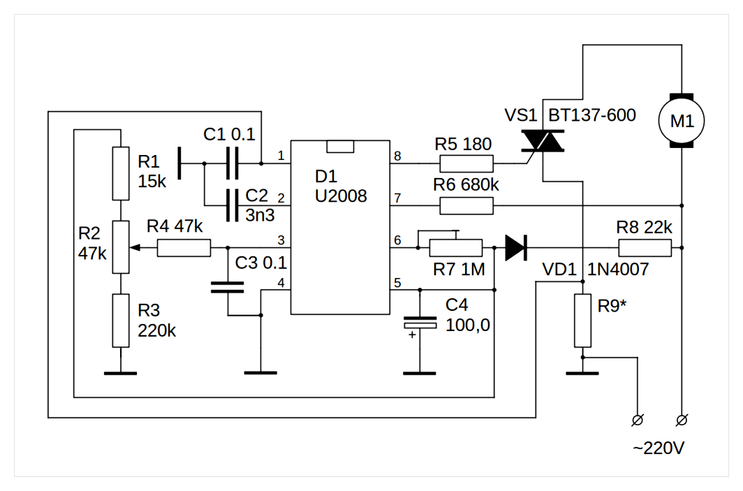
Most of the parts used in the circuit: MLT-0 resistors.25, capacitors K73-17.
WARNING! Resistor R2, regardless of its design, should have a well insulated knob. It has a direct connection to the mains.
Capacitor C4 K50-35 type for voltage 50 V. Note that pin 5 of the D1 chip is a negative voltage. The common wire in circuits is usually the minus wire, but here it is plus. Resistor R5 MLT-0.5, R7. better to use a multi-turn film resistor. Diode D1 can be KD105B, V or similar. Resistor R8 is MLT-2, it will be noticeable power loss. The resistor R9 is discussed below.
Circuit work
The U2008B chip is a voltage regulated phasor. It provides a choice between soft start function and speed stabilization. On a conclusion 1 it is applied a signal from the current sensor or if using a soft starter, is connected an electrolytic capacitor in capacity of some microfarads.
To pin 2 connect the capacitor of the phase shifting circuit. Output 3 is the input of triac angle regulator. The bigger this angle, the later the triac opens in each half period and the less energy is delivered to the controlled load. Pin 4 is the common ground for the circuit. It should not be confused with physical earth or ground. Pin 5 is the power supply of the microcircuit, from the rectifier on resistance R8, diode D1 and capacitor C4.
Pin 6 is the minimum opening angle of the triac. It is adjusted so that at the extreme position of resistor R2 in the load the maximum power is achieved. Pin 7 is the input for the mains voltage sensor. The chip uses it to compensate for phase shifts and determine the auto-restart level. Also internally on the chip is the load current protection.
Pin 8 is the output of the triac control pulses.
The resistor R9 is selected so that the voltage on it was. 250 mV. To do this you need to know the current flowing through the motor. It can be determined by dividing the power by the line voltage. For example, for a 600 watt output, the current will be 600/220 = 2.72 А. Then R9 = 0.25/2.72 = 0.09. Resistor 0.1 Ohm can be made from a piece of NiCr wire thick enough not to heat up.
The circuit given will stabilize the speed of rotation, making it independent not only of the mains voltage, but also to a good degree from the load on the angle grinder’s disc. If you need only soft start, you need a jumper instead of R9, and C1 must be replaced with an electrolytic capacitor with a capacity of 22 100 mF. It is necessary to connect the minus line of the capacitor to pin 1 of the microcircuit.
Assembly procedure
For the assembly it is best to use printed circuit boards. This holds the parts together. The diagram above is drawn in such a way that it can tell you how to place the parts. all the leads of the chip go from the key in a circle in ascending order. Because of the need to cool the triac, the board cannot be smaller than a matchbox.
It is necessary to cool the triac, because in more or less powerful models of angle grinder it will have about 10-15 W of power. Therefore, it is necessary to provide space for an aluminum radiator for the triac. Draw the wiring diagram on a sheet of life-size paper and use the puncher to transfer the pin holes to the workpiece of foilized textolite. Drill the holes with a mini-drill and use drill bits of the appropriate diameter for the pins of the components.
Then, from the side opposite the installation of the parts, carefully draw the tracks with nitrolac, taking care that they are not shorted to each other. After the board dries, pickle it with a solution of ferric chloride or copper sulfate with ordinary kitchen salt. The etched board should be carefully washed with plenty of water and dried. The dried board is zalizhivayut, using rosin and solder.
The leads are also tinned before soldering onto the board, taking care not to overheat the semiconductor parts, especially the microchip. Before tinning you can wipe the leads with alcohol, this can greatly help the quality of the tinning, especially if the leads have been touched with your hands.
TIP: In jobs like chemistry, tinning, and soldering, a person’s hands are always dirty by definition. The slightest trace of grease will tarnish the tinning surface and make it difficult for the flux to work. Do not touch tinning surfaces with your hands, use tweezers.
How to connect the device to the angle grinder, options
Connection of the regulator depends on which type of device is selected. If using a simple circuit, it is sufficient to mount it in the power supply channel of the power tool.
Installing a homemade circuit board
There are no ready recipes for assembling. Everyone who has decided to equip an angle grinder regulator, have it according to their goals and the model of the tool. Some people put the device in the handle of the holder, some in a special additional box on the housing.
In different models, the space inside the housing of the angle grinder may be different. Some have enough free space to install the control unit. In others, you have to take it to the surface and fix it in another way. But the trick is that, as a rule, there is always a certain cavity in the back of the instrument. It is intended for air circulation and cooling.
This is usually where the factory speed regulator is located. The handmade circuit can be placed in this space. In order not to burn out the regulator, thyristors should be installed on the radiator.
Features of mounting a ready-made unit
When buying and installing the factory regulator inside the angle grinder, most often it is necessary to modify the housing. to cut a hole in it for the output of the regulating wheel. But it can have an adverse effect on the stiffness of the casing. That is why it is preferable to mount the device outside.
The adjusting wheel changes the speed
The numbers on the thumbwheel indicate the number of spindle revolutions. This value is not absolute but relative. “1”. minimum revolutions, “9”. maximum revolutions. The other digits are for orientation during adjustment. The position of the thumb wheel on the housing can be different. For example, on an angle grinder Bosch PWS 1300-125 CE, Wortex AG 1213-1 E or Watt WWS-900, it is located at the base of the handle. On other models, such as the Makita 9565 CVL, the adjustment wheel is in the end of the hood.
Scheme of connection of the regulator to the angle grinder is not complicated, but sometimes it is not so easy to pull cables to the button, which is located at the other end of the body of the device. The problem can be solved by selecting the optimum cross section of the wire or bringing it to the surface of the housing.
A good option is to mount the controller on the surface of the device or attach it to the mains cable. Not always everything works on the first try, sometimes the device has to be tested and then some adjustments have to be made. And it’s easier to do this when its components are accessible.
Important! If there is no experience with electrical circuits, it is advisable to buy a ready-made factory regulator or angle grinder, equipped with this function.
Why is an angle grinder a soft starter and speed regulator??
In modern angle grinders use 2 necessary options that increase the characteristics and safety of the equipment:
- speed regulator (frequency converter). a device designed to convert the number of revolutions of the motor in different modes of operation;
- soft starter. a scheme that provides a slow increase in motor speed from zero to the limit value when connecting the machine.
Are used in electromechanical equipment, in the structure of which the alternating current electric motor with collector is practiced. Help reduce wear and tear on the machine’s mechanical parts when switched on. Reduce the strain on the machine’s electrical components by putting them into operation smoothly. Studies of material properties have shown that the strongest wear and tear of the contacting parts occurs during the sudden transition from a stationary state to a fast activity. For example, one start-up of an internal combustion engine in a car equals the wear of the piston and the group of sealing rings to 700 kilometers of run.
When power is applied, the machine undergoes a stepwise transition from standstill to wheel spinning at a speed of 2,500 to 10,000 rpm in 60 seconds. To those who have used an angle grinder, the feeling that the tool directly “flies out of his hands” is well known. Just at this moment, and most of the accidents involving the unit’s mechanical parts happen.
Rotor and stator windings feel just as much strain. The alternating current motor with the collector starts in the short circuit mode, the EMF is already pushing the shaft forward but the inertia force does not yet allow it to rotate. A surge of inrush current is generated in the motor coils. Even though they are designed for this kind of work, in time there comes a moment (for example, in case of a voltage drop in the mains), when the insulator of the winding can not withstand and a short circuit occurs between the coils.
When soft-start and frequency changing circuits of the motor are introduced into the electric circuit of the tool, all the above mentioned troubles disappear spontaneously. In addition the problem of a sudden and significant voltage drop in the mains during the tool start-up is solved. It is clear from this that household appliances will not be in danger of failure. A circuit breaker on the electricity meter will not work and turn off current in the apartment or house.
Soft-start circuit is applied in middle and high price segment angle grinders, the knot of speed regulation. more and more in professional versions of angle grinders. Speed regulation allows you to process angle grinder soft materials, to perform delicate grinding and polishing, because at high speed wood or paint is simply burned. Auxiliary circuitry increases tool price, but extends service life and degree of safety in use.
The simplest regulator scheme
Electric circuit of the speed regulator for angle grinder is assembled on the circuit board or in hinged mounting. And the printed circuit board can also be made by yourself using textolite and bleach for etching. A mixture of hydrogen peroxide, salt and citric acid can be used instead of iron.
Diagram of motor speed regulator for angle grinder
Wiring configuration
- resistor R1 (4,7 kOhm);
- symmetrical thyristor DIAC (DB3);
- symmetrical thyristor TRIAC (VT-136/138);
- trimmer resistor VR1 (500kOhm);
- Capacitor C1 (0.1μF400V).
Working principle
The circuit working principle is as follows. VR1 is responsible for the charging time C1. When voltage is applied to the circuit, thyristors are closed and the output is 0. As the capacitor charges, the voltage in the capacitor increases and opens the DIAC, which gives voltage to the TRIAC. It also opens and allows current to flow. then both thyristors are closed and stay in this position until the full reverse charge of C1. As a result, the output is a complex wave signal with an amplitude directly depending on the operating time of the circuit C1-VR1-R1.
Speed regulator connection diagram
Final assembly and testing of the regulator
A circuit is assembled on a printed circuit board or heat sink made of copper (aluminum). At mounted assembly it is especially important place of thyristors installation (strictly on a radiator, it plays a role of heat sink). Then there is a mandatory check of the availability of the circuit with an ordinary light bulb. The smoothness of variation of incandescence will be the same as in the finished regulator turns for angle grinder after final assembly.
The factory models include a plastic adjustment wheel, if desired, you can also buy it separately and include it in the kit homemade regulator. If the test was successful, the regulator is mounted on the angle grinder and cut into the power circuit of the tool.
Installation of the regulator on the angle grinder
Speed regulator for angle grinder with their own hands can be mounted in four variants:
Regulator installation on the angle grinder. scheme
- in the handle;
- into the outer box which is mounted in a convenient place on the tool body;
- into a cavity for cooling (manufacturers use this option);
- on the power cord.
Installing an additional box does not require cutting the housing to output the regulator, but the place should be chosen very picky, so that the innovation does not interfere with a convenient way to hold the tool. Mounting into the handle or cooling cavity will require cutting a hole for the outlet of the adjustment wheel, here the main thing is not to lose the rigidity of the protective cover and well grind the edges so as not to hurt your hands when working.
Often the best solution is to attach it to the wire. In this case, the regulator is easy to test, no need to think about the place and method of attachment (duct tape and plastic housing will do quite well). If desired, it can always be removed and redone.
The main malfunctions of angle grinder and their causes
Statistically, most cases of angle grinder failure are related to the electrical part of the machine. Some failures may be minor, which allows you to repair the angle grinder with your own hands. But, for example, when the burnout of the motor windings repair angle grinder can make only a specialist.
angle grinder does not turn on
The causes of the fact that the angle grinder does not turn on, may be the following:
- the electrical plug is faulty;
- the electrical cable is defective;
- the start button is broken;
- The contact between the power cable and the button is broken;
- breakage of the contact wire of the electric brush;
- severe wear and tear of the electric brushes;
- rotor or stator winding failure.
the angle grinder does not develop speed
Causes of the fact that the angle grinder does not pick up speed, can be different.
- Failure of the block of speed control. To check this version, you need to connect the motor of the machine directly, bypassing the regulator, and check the operation of the device.
- Electrical cable failure due to permanent kinks or mechanical damage. This causes the damaged wire to begin to warm up under load and the engine speed to drop.
- The collector is contaminated with dust. It is necessary to remove impurities with alcohol.
- Brush problems. They may be worn out or have a short contact wire as shown in the following photo.
Brush is half worn out but still functional. The short contact wire does not allow the spring to press the electrode against the collector. This situation can also be the reason why the angle grinder stops working normally.
The electric motor is heating
The causes of the fact that the angle grinder heats up, may be.
- Incorrect operation mode of the device. Overloading can cause the motor to become very hot, often causing the windings to burn out.
- Destruction of the bearings on the armature. As a result, the rotor is caught in the stator, motor operation is hindered and the windings overheat. The problem can be solved by replacing the bearings.
- Clogged air ducts through which air flows to cool the motor. The ventilation openings need to be cleaned of dust.
- Breakage of the impeller, which is used for cooling the engine. Winding installed on the rotor, on the opposite side with respect to the collector. If the impeller is broken, it must be replaced with a new one.
The angle grinder sparks
If you notice a strong sparking when you turn on the angle grinder in the area where the collector is located, then the causes of this trouble may be.
- Damaged armature winding: breakage of one or several winding sections, intertwist short circuit. Such failures cause excessive noise, engine speed drop and brushes burn.
- The contact between the collector plates and the winding is broken.
- Weak pressure of brushes. With long modes of the angle grinder springs overheat and can “anneal”, losing their elasticity.
- Motor rotor out of balance.
- Cylindrical surface of the collector disturbed. This sometimes occurs after rewinding if the armature is not turned on the lathe, but installed directly into the machine. Brushes may also be observed to spark excessively in such a case.
- Insulation between manifold lamellae is broken. This may also result in the slots in the track being blocked by graphite or in a leak between the lamellae.
- Bearing wear that causes the rotor to run out also causes excessive brush arcing.
- Armature shaft geometry malfunction. This usually occurs if the motor is disassembled incorrectly and the shaft is bent.
- Wrong brand of graphite brushes installed. Brushes selected according to speed and voltage to be expected.
- Lifting one or more lamellae causes the brushes to burn out quickly. This may be caused by overheating of the motor in continuous operation. As a result, the glass mass that serves as the base of the manifold softens and the blades begin to lift. Because the blades are raised, the brushes wear out very quickly.
Design features of the tool
Interskol is a Russian leader in the development, production and sale of various power tools, recognized by the world manufacturers. Interskol products are distinguished by their ergonomics, simplicity and ease of maintenance, environmental friendliness, higher power. Interskol angle grinders are classified by wheel diameter: 115,125,150,180,230. Among those who like to make their own hands are particularly popular are two classes of Interskol angle grinders: with a disc diameter of 125 mm and 230 mm. There are several models in represented classes with different power capacity. Interskol has four (4) models in the 125 mm class: 125/900 angle grinder, 125/1000 angle grinder, 125/1100E angle grinder, 125/1400EL angle grinder. There are ten (10) Interskol models produced in the 230 mm class, which differ from each other in power. The Interskol 230 angle grinders are available in powers exceeding 2,000 watts.
Interprets the marking Interskol angle grinder 230/2300: angle grinder with a maximum circle diameter of 230 mm, power 2300 watts.
At Interskol angle grinders Interskol angle grinder 125 driven gears are mounted on a spindle by means of keyed joint. Interskol angle grinders Interskol 125 angle grinder are assembled in one body, which serves as a handle.
Interskol angle grinder 230 angle grinder has a handy back handle at the back of the body. These are powerful professional machines with a two-handed design. Angle grinders of this class have driven gears pressed on the spindle shaft.
In the proposed repair instructions, we will review the schematics of the two classes of Interskol angle grinder: 125 angle grinder, 230 angle grinder.
Interskol angle grinder controller installation
Speed regulator for angle grinder with their own hands can be mounted in four variants:
Installation of the controller on the angle grinder. scheme
- into the handle;
- in an external box, which is mounted in a convenient place on the body of the tool;
- In the cavity for cooling (manufacturers use this option);
- on the mains cable.
Installation of an additional box does not require cutting of the housing for the output of the regulator, but the place should be chosen very meticulously, so that the innovation does not interfere with the convenient holding of the tool. Mounting into the handle or cooling cavity will require a hole to exit the adjustment wheel, here the main thing is not to lose the rigidity of the protective cover and well grind the edges so as not to hurt your hands when working.
The wire fastener is often the best choice. In this case, the regulator is easy to test, no need to think about the place and method of attachment (duct tape and plastic housing will do quite well). It can always be removed and rebuilt if desired.
How to make with your own hands
Even a novice hobbyist will be able to assemble the RPM regulator according to the schematic. Components for making such a device can be purchased at any specialized stores. In addition, they can be removed from the old, unnecessary board (in this case it is recommended to check them for proper functioning). To make the speed regulator yourself it is necessary:
- Assemble according to the instructions on the circuit board (thyristors are recommended to install on a copper or aluminum radiator).
- Using an ordinary incandescent lamp perform a test of the assembled circuit for its functionality. After using this device and adjusting it, the incandescent lamp level should change.
- Install the finished product on the angle grinder.
At the final step you need to make a preliminary test of the homemade regulator. If the device works successfully, without failure, then it should be secured, and then close the cover. If during the creation of such a homemade device a simple circuit was used, then it can be mounted in the channel, where the mains supply of the angle grinder is located.
It should be noted that there is no ready-made solution for mounting the controller board in the angle grinder. This is due to the fact that in different models of angle grinders, the free space can also be different. In some cases, if the free space directly inside the enclosure is not enough to install the board, then it is mounted on its outer part.
However, it should be noted that in almost all models of angle grinders, there is a small hollow in the form of a cavity in the area of the back. The main purpose of such a cavity is that it provides air circulation and is part of the cooling system of the power tool. This is usually where the factory speed controllers are installed. Therefore, in the same place you can mount your own handmade circuit.
What is a soft starter
Smooth start of the angle grinder is a stepped voltage supply to its motor at which it accelerates without surges of starting current and with a gradual increase in torque. This mode protects the supply line from excessive current draw and prevents it from “sagging”. This is especially important if the angle grinder is powered from an autonomous voltage source. It also protects the motor windings from excessive currents that could lead to breakdown. With a smooth start, the gearbox of the angle grinder is not subject to shock loads, which protects it from premature wear.
The electronic circuit that provides a soft start of the angle grinder is built on the same principle as the speed regulator circuit. A triac is also used here to limit the power to the electric motor. But in contrast to the speed controller the control pulses to the triac are not formed by manual setting of resistance in the RC-chain, but by electronic circuit, which forms a sequence of pulses with decreasing delay time. The diagram below shows how the pulse shift time is reduced and the power supplied to the angle grinder motor increases.
Since the soft starter and the speed regulator work on the same circuitry, there are electronic units that combine the functions of both of these devices.
Installing a homemade circuit board
Unacceptable ready-made assembly recipes. Whoever decided to equip an angle grinder with a regulator, has it according to their purpose of the tool model. Someone inserts the device in the handle holder, someone in a special additional box on the body.
In different models, the place inside the body of the angle grinder and possibly different. In some fairly free space for installation of the control unit. In others, you have to take it to the surface and reinforce it with another method. But the trick is the fact that, usually, in the back of the tool always exists a certain cavity. It is designed for air circulation and cooling.
This is usually where the factory speed controller is located. You should of course put your own circuit in this place. In order not to burn out the regulator, thyristors should be installed on the radiator.
Speed controller for angle grinder with their own hands
Although the creation of a speed regulator for angle grinder little, who is necessary, there are still models that have made manual adjustment of disk speed. The regulation of the angle grinder is much different from an electric electric screwdriver or drill, because:
- A completely different grip is used throughout the work.
- Do not adjust during operation. Adjustment should only be carried out with the machine switched off.
The speed of the blade must be adjusted
- When cutting metal (regardless of the thickness of the material), the result of the work carried out depends on the speed of the disc. If you are cutting thicker material, use the highest possible speed. If you are working with thin material, lower the speed if possible, since a high speed would wash out the surface of the disc.
- When cutting tiles at high speed, it is dangerous. Also the disc, rotating at high speed, begins to beat off small pieces of material, thereby making its surface brittle. Since the stone has a variety of types, a certain speed is used for each type. For many minerals, high RPMs are used.
- If you are grinding or polishing, then adjusting the speed of the angle grinder is just necessary. If the revolutions are set incorrectly, the surface of the material will be spoiled. For example, the material that has a paint coating can be spoiled.
- If you constantly use discs that have different diameters, then a speed controller for the angle grinder must be available. If you change the angle grinder disc to another disc that has a larger diameter, the speed should be reduced. You can’t hold a grinder that has a disc with a huge diameter.
- The choice of speed of rotation when polishing concrete material is dependent on the use of a particular type of crown. The torque must not be reduced by lowering the RPM.
- If you use a diamond disc, its speed must be reduced, otherwise the surface will begin to fail due to overheating. Of course, if you are using an angle grinder to cut pipes, angles or profiles, then having a regulator is not necessary. But if the angle grinder is used for a variety of purposes, then the speed regulator for the angle grinder is a must. All of these reasons show that having an angle grinder regulator is a must.
Angle grinder regulator description
The angle grinder’s regulator is a rheostat (variable resistor) that reduces the voltage (all done by the regulator). You need to control the amperage, because if you reduce the number of revolutions, there will be a decrease in the power of the construction machine. Consequently, there will be a reduction in torque. As a result, it will become a small value of voltage, and at a certain resistance of the electric motor will not be able to turn the shaft. Therefore, it is necessary to follow a certain scheme: The scheme of the angle grinder is made up of a soft starter module and directly the speed regulator.
Modern advanced models have a distinctive electronic system, and not everyone can afford to buy it.
Making your own regulator
How to make the regulator on their own? The desire to attach an ordinary electronic device designed to change the electric power (dimmer) ends up with nothing. First of all, the dimmer for the angle grinder is designed for a different load. Also, the dimmer has no overlap with the control of the electric motor winding. Therefore, it is necessary to carry out the installation of a separate circuit. It is also necessary to figure out where it will be located inside the body of the angle grinder.
An important point: if you do not have any experience with electrical circuits, it is best to buy a ready-made regulator for angle grinder or angle grinder with the presence of this function.
A simple semiconductor device (thyristor controller) can be constructed by your own hands. This procedure will require 5 radio elements. You can buy radio elements at the radio market. Due to the compactness, you can safely hold the prepared circuit in the angle grinder, without damaging the ergonomics and reliability. However, the torque is not saved by reducing the RPM on the angle grinder. This option is best suited for machining soft metals, as well as tinplate, which has a small thickness.
If you are machining stone, you need to install a disc that is 180 millimeters in size. Next, you need to create a more complicated regulator circuit. In this scheme, the control module will be the chip KR1182PM1. This scheme has control over the amperage at different revolutions, and also makes the loss of torque minimal when decreasing the revolutions. When using this circuit, the operation of the motor is increased.
If the angle grinder is used as a circular grinder, you must equip the angle grinder with a connection point. Thanks to such a point, the connection is made, and you can regulate the speed remotely. You will get a great homemade speed regulator.
How you made the regulator does not depend on the fact that it is a mandatory component of the angle grinder, which makes the possibilities of work wider and allows you to comfortably use this construction tool. Also, after installing the regulator, you should do a test run of the angle grinder to see if the construction tool pulls out of your hands. External speed regulator for angle grinder with your own hands can be made.
How to assemble an adjustment circuit?
The traditional speed control circuit is quite simple: pulse-phase unlocking of a triac, it has only a few parts. However, it is not very stable, so a professional tool uses this principle in a more complicated version, with feedback and overcurrent protection (U2008B and U2010B chips).
Now there are more advanced variants, using PWM regulators. Their circuits are a little more complicated, but the main difficulties there are in setting up and assembling. May require instrumentation (oscilloscope), and the ability to work with expensive parts that are afraid of static charges. In general, it is not for ordinary consumers.
So it is better to take a middle solution: a variant with a triac and a U2008 chip, this circuit will only require a proper assembly and inexpensive parts. An uncomplicated device, but for a household tool it works just fine.
Circuit Diagram
The circuit diagram is shown in the figure below:
Most of the parts used in the circuit: MLT-0 resistors.25, capacitors K73-17.
WARNING! Resistor R2, regardless of its design, must have a well-insulated knob. It has a direct connection to the mains.
Capacitor C4 type K50-35 for a voltage of 50 V. Note that pin 5 of chip D1 has negative voltage. Usually in circuits the common wire is minus, but here plus. Resistor R5 MLT-0.5, R7. better to use a multi-turn film resistor. Diode D1 can be KD105B, V or similar. The R8 resistor is MLT-2, it will have a significant power loss. Resistor R9 is discussed later.
Circuit operation
The U2008B chip is a voltage regulated phasor. It has a choice of soft start function or speed stabilization. On pin 1 is a signal from the current sensor or if using a soft starter, an electrolytic capacitor with a capacity of several microfarads is connected.
Why do you need to regulate the speed of the angle grinder disc??
This is what the speed regulator board looks like assembled
The engine speed regulator is not just a variable resistor that lowers the voltage. It is necessary to have electronic control of current value, otherwise with decrease of revolutions power and torque will proportionally decrease. In the end, there will come a critically low value of voltage, when at the slightest resistance of the disk, the electric motor simply can not turn the shaft. Therefore, even the simplest regulator must be calculated and made in the form of an elaborate circuit.
And more advanced (and therefore expensive) models are equipped with regulators based on integrated circuits.
Integral circuit of the regulator. (the most advanced variant)
If we consider the electrical diagram of the angle grinder in principle, it consists of a speed controller and a soft starter module. Power tools equipped with advanced electronic systems are significantly more expensive than their simple counterparts. That is why not every home handyman is able to buy such a model. And without these electronic blocks there would only be a winding of the electric motor and the trigger.
The reliability of modern electronic components of the angle grinder exceeds the life of the motor windings, so do not be afraid of buying power tools, equipped with such devices. The only limitation is the price of the product. Not only that, but the users of inexpensive models without a regulator sooner or later come to install it themselves. The unit can be purchased ready-made or make it yourself.
Making a speed regulator with your own hands
Trying to adapt a regular dimmer to adjust the brightness of the lamp does not work. First of all, these devices are designed for a completely different load. Secondly, the principle of operation of dimmer is not compatible with the control of electric motor winding. So you have to install a separate circuit and figure out how to put it in the tool body.
The simplest thyristor speed controller can easily be made by yourself. You need five radio elements, which are sold at any flea market.
Schematic diagram of a thyristor speed controller for your tool
Compact design allows to place the circuit in the housing of angle grinder without compromising ergonomics and reliability. But this scheme doesn’t save torque if rpm drops. This variant is suitable for lowering the speed when cutting thin tinplate, polishing work, machining soft metals.
If your angle grinder is used for processing stone, or it is possible to install disks larger than 180 mm, you need to build a more complex circuit, where as the control module uses chip KR1182PM1, or its foreign analogue.
Circuit of the speed regulation with the use of chip KR1182PM1
This circuit controls the current at any revolution, and allows you to minimize the loss of torque at their decrease. In addition, this scheme is more respectful to the engine, prolonging its service life.
The question of how to make the tool’s RPM adjustment arises when it is stationary. For example, when using an angle grinder as a circular saw. In this case the regulator is equipped with a connection point (automatic unit or socket) and the RPM is regulated remotely.
Regardless of the method of execution, the speed control of the angle grinder expands the capabilities of the tool and adds comfort when using it.
Types of faults in the electrical and mechanical parts of the drill
The most common problems with the electrical component are when the drill sparks on the brushes due to significant abrasion or wear. Appliance with badly worn brushes will not turn on at all. The sign of problems with the motor. no signs of its switching on (sound, vibration, etc.). In a drill with speed control, reverse and speed control may stop working.
Mechanical faults. bearing or gear mechanism failure, shaft failure. They are manifested by humming, periodic stops of the device, slow rotation. Sometimes there are problems with the chuck: difficulty in disconnecting the drill, unscrewing the chuck from the shaft.
Necessary tool
Planning the procedure of repairing the drill with your own hands, you will need to prepare the following tools:
- screwdriver with attachments;
- vice;
- bearing puller;
- Wrenches for nuts and ends;
- emery cloth for sanding;
- ohmmeter and megger;
- pliers;
- caliper.
To competently make an independent repair drill, you need to imagine the device its electrical and mechanical stuffing. In this case, most faults can be repaired at home.